The design of earthworks, i.e. structures built using loose soil, has as its main objective the creation of constructions that remain stable over time, guaranteeing adequate safety margins. The performance required varies according to the type of work: for example, for an earthen dam or a river embankment it is essential to ensure hydraulic impermeability, while for road or railway embankments it is necessary to guarantee safe passability.
In general, in the construction of road embankments, preference is given to the use of materials that naturally possess suitable characteristics. On the other hand, materials that do not originally conform but could be made suitable through treatments with additives are not considered. Currently, regulations regarding the design and construction of embankments prescribe the use of materials that meet specific natural requirements, without considering mechanical modifications that can be obtained through processing or treatment. This poses a challenge, as it is often complex to find selected, high-quality soils for embankments construction.
Soil transport refers to the transport of materials from the quarry to the construction site where they will be used. To reduce the costs associated with these operations, regulations are gradually evolving to allow the use of non-conforming materials, which were previously considered waste. These materials, after being treated with additives and subjected to compaction, can improve their mechanical properties and become suitable for use in road embankments.
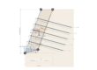
Geometric characteristics
The figure shows a schematic cross-section of a standard embankment

A road embankment consists of the following structural elements:
- Foundation layer;
- Embankment body (central core);
- Road subgrade;
- Road superstructure or pavement.
Stability and collapse
The stability of embankments, as with other earthworks, is closely linked to the interaction with the foundation soil. The loads transmitted from the embankment to the ground can reach several tens of tonnes per square metre, affecting even very deep layers of soil. If the laying surface is inclined, the risk of slipping can increase. On soils with good mechanical properties (e.g. rocks or cemented granular soils), the stability of the embankment depends mainly on its structure. However, if built on weak soils, the risk of instability must be assessed and possible subsidence, both immediate and over time, due to soil compression must be considered.
Embankment instability can occur when the foundation soil has a low strength. The so-called ‘bearing capacity’ is the point beyond which the soil can no longer support the weight of the embankment, causing a general failure, characterised by a sliding surface in the soil that gives way under the weight of the embankment. Stability is assessed using geotechnical methods and requires a safety coefficient set by the designer.

Unconsolidated saturated clay soils are particularly vulnerable to sliding phenomenon, especially in the early stages of embankment construction, due to internal pressures that take a long time to dissipate. In these cases, common remedies include reducing the height of the embankment, softening the slopes or constructing lateral counterweights.
Another problem is subsidence, which can occur after the construction of the embankment due to material compaction, traffic vibrations and subsidence of the foundation soil. Factors such as inadequate compacting or the use of unsuitable materials can cause excessive deformations, compromising the road pavement.
The phenomenon of foundation soil consolidation can cause subsidence to occur over varying periods, from a few months to many years, depending on the characteristics of the soil and the height of the embankment. When subsidence is not uniform, it can damage the road superstructure. In such cases, it is necessary:
- Carefully analyse soil characteristics and predict subsidence;
- Decide whether to accelerate subsidence to stabilise the embankment or try to reduce it.
Computation of embankments
Starting with version 2025 of GeoStru Bearing capacity and settlements – Loadcap, t allows all useful verifications for the stability of embankments to be carried out. They include:
- Safety verifications in respect of SLU:
- Calculation of vertical design resistance
- Crushing verification
- Slip verification
- -Global stability verification
- SLD, SLE verifications:
- Calculation of elastic and edometric yielding (also from edometric curve) in x,y,z
- Course of settlements over time
- Consolidation interventions:
- Gravel piles: Recalculation of limit load and subsidence
- Lowering the water table with the application of gravel piles (drainage system)
All verifications are carried out according to Eurocode 7 and 8.
The application of road embankments in GeoStru Loadcap makes the approach to the embankment-soil interaction problem totally different from the foundation-soil interaction: the geotechnical relationships used for the embankments are created specifically for the type of problem.
Embankment configuration
From the ‘General Data’ menu, as mentioned, you can reach the new instrument:

After entering the stratigraphy of the terrain, from here it is possible to size the embankment and, very importantly, possibly insert drains in the form of gravel piles to reduce the hydraulic load and thus consolidate the soil forming our embankment more quickly.
In fact, the most common solutions for dealing with subsidence include:
- Increasing the overburden: build the embankment with a greater height than necessary and then reduce it once the subsidence has stabilised. It is an economical but slow technique.
- Drainage systems: install vertical or horizontal drains to facilitate the release of water from the ground, reducing consolidation time. Vertical drains, made of sand piles, are the most commonly used.
Under Properties, the geotechnical characteristics of the embankment can be set:
- Description: a short free description identifying the work and, alongside, the possibility of setting the colour of the latter in the template;
- Specific weight expressed in KN/m3;
- Angle of friction expressed in °;
- Cohesion expressed in kPa.
In embankment geometry, it is possible to define the longitudinal length, upper and lower base and height all expressed in m.
In the soil and water table profile, you will indicate in m how far you want to extend the soil underneath the embankment to the left and right of it: EL and ER.
The option Active Gravel Piles allows you to activate or deactivate the gravel pile action. By selecting it, the subsequent Gravel Piles part will be deactivated.
In this last section, if active, you will enter and set all the parameters to describe the gravel piles for drainage effect such as:
- Diameter and length in m;
- Colour of piles to be displayed in the diagram;
- First and last pole X position: in the two input boxes, the distance at which the first (left cell) and the last pole (right cell) must be positioned, respectively, with respect to the origin of the embankment diagram (i.e. from the lower left extreme along the X axis);
- First and last pole Z position: in the two input boxes, the distance at which the first (left cell) and the last pole (right cell) must be positioned respectively in relation to the origin of the survey layout (i.e. from the bottom left-hand corner along the Z axis normal to the PC screen);
- Spacing X,Z: Once you have defined the position of the first and last pile along the X and Z directions, and thus have created the spacing of the poles, you can enter the spacing of the poles along X (left input) and Z (right input) in m;
- Modulus of elasticity expressed in MPA in a recommended range of 250 to 500;
- Single pile limit load: expressed in KN.
Under Water table it will be specified whether the water table is present or not through the Water table depth from the natural terrain level expressed in m, if it is different from 0 it will indicate its presence and the option Calculate water table lowering will be activated: by clicking with the mouse, the lowering that the water table will undergo will be calculated depending also on the other two parameters to be entered, such as Total extracted flow rate in m3/s (in the case of the presence of extraction wells) and the permeability of the ground expressed in m/s in the recommended range of 10-9 – 10-2.
The option ‘Calculate self-weight and add it to the net load’ allows the own weight of the embankment itself to be taken into account in the calculations in addition to other loads such as,for example, road overloading


Pile and Micropile – MP software for calculating vertical and horizontal bearing capacity and settlement of piles: infixed including truncated and drilled; micropiles: tubifix and root: jetgrouting, and helical.
Nonlinear finite element stress calculation and design of structural sections at ultimate and serviceability limit state.
Bearing capacity of embedded piles in rocks in according to Pérez Carballo
With MP you can calculate the limit load of gravel piles
Bearing capacity calculation
From the Calculation menu, clicking on Bearing capacity calculation will open the usual limit load calculation window.
It should be noted that, in the case of embankments, the section on acting loads is different from the other cases: in fact, it is only necessary to indicate the normal design pressure in kN/m3 and the type of load applied between the Design or Service limit state
The results will be displayed for each author and the most unfavourable condition will be highlighted.


Calculation of settlements
The special feature of the new update also lies in the calculation of settlements: in fact, the calculation approach is three-dimensional. This is easily verified by going to Calculation and then Edometric and Schmertmann settlements.
In the following image, the planimetric view of the calculation scheme is shown, where the yellow part is the area occupied by the embankment and in white is the remaining terrain. By clicking the left mouse button and holding it down, the user can move planimetrically, i.e. along X and along Z, and view the subsidence value Wt (which would represent the Y axis).
Three-dimensional settlements is also calculated by applying gravel piles as drains

The global stability analysis of embankments with Slope and the export of geometry for import into GFAS
Also very important is the interoperability with other GeoStru software.
In the Output Menu there is the ‘Export Slope’ tool: once pressed, a file with the extension ‘LoadcapToSlope’ will be generated, which once saved will be opened with the Slope/Loadcap module, from which the global stability analysis can be performed.
Similarly, the interoperability of data between Loadcap and Geotechnical and F.E.M. analysis system – GFAS for finite element analysis of the embankment, including analysis by construction phases, makes it possible to generate the file in *txt format, containing the geometry to be imported, as mentioned, into GFAS.


3D visualisation
The outline of the embankment, with any drains, can be viewed three-dimensionally


Loadcap is a software for drawing up professional geotechnical reports. It calculates the bearing capacity and settlement of foundations in loose and rocky soils according to the methods of: Terzaghi (1955), Meyerhof (1963), Hansen (1970), Vesic (1975), Brinch-Hansen (1970), Richards (1993) and Meyerhof and Hanna (1978) and more.
Starting with version 2025, LoadCap carries out the design of road and rail embankments. The verifications performed include: Bearing capacity, Failure (3D), Failure over time, Consolidation with gravel piles and Drainage