When carrying out the stability analysis of a slope using the well-established software Geostru Slope Stability analysis – Slope, the user has the option of placing a retention structures of his choice : Walls, Piles, Ground Anchor and Reinforced soil. Selecting the latter will open the module Reinforced Earth – MRE. We speak of a module yes, but we can safely call MRE a separate software, and I will explain why below.
MRE is a free software application as part of Slope
Many users are not aware of this, or those who intend to purchase Slope are not aware that, unlike other software packages, it includes the totally free MRE reinforced earth design and verification software. The latter, as we shall see, allows the design and verification of reinforced and reinforced earth, which in turn can be used as an intervention work in the stability analysis of the slope under study.
In Slope, in the “Tests-Loads-Intervention works” menu, just click on “Intervention works”, the side window of the same name on the right will be activated, and from here clicking on the text “Reinforced earth” will launch MRE.
The same result is obtained by pressing CTRL+E in Slope.


Slope stability software carries out the analysis of soil or rock slope stability both under static and seismic conditions, using the limit equilibrium methods of Fellenius, Bishop, Janbu, Bell, Sarma, Spencer, Morgenstern & Price, Zeng Liang, Discrete element method (DEM).
Discrete elements method for circular and non-circular surfaces by which it is possible to ascertain slippages in the slope, examine a gradual failure, and employ various models of force-deformation relationship.
Input of seismic data, geometry, water table, loads and soil parameters
Once MRE is started, the modelling of the reinforced earth or reinforcement goes down to the smallest detail without omitting anything.
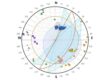
From the GENERAL DATA you can set the seismic parameters and the type of calculation: by choosing “Verification” you can enter the desired reinforcement lengths. By choosing NTC 2018, the combinations are already ready in the calculation phase.
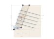
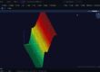
Under GEOMETRY it is possible to assign the geometry of the STRUCTURE (reinforced earth), which can be generated automatically by entering values for the height, width and inclination of the upstream and downstream faces (parallelepiped geometry), or by entering the coordinates in the grid, if you wish to have a customised shape (e.g. with berms). Remember that a defined “block” must be created in the geometry and not just the topographic profile: therefore in addition to the profile, the line defining the upstream face of the structure must also be entered
LOADS are considered as distributed loads applicable as load strips on the embankment.
In SOIL DATA the geotechnical parameters must be entered: those of the structural embankment (soil between the reinforcements), those of the soil in the site excavated and pushing on the reinforced block and, finally, that of the foundation.

Reinforcements
The crucial point is the definition of reinforcements. In MRE there is by default an archive of reinforcement types, which can be viewed from the tool of the same name, which the user can modify by adding others. Once a new reinforcement has been defined, it will be available from the drop-down menu when defining the position.
Specifically then:
- Under REINFORCEMENT POSITION, the height distribution of the reinforcements is established, as well as the type of reinforcement to be used. There is an automatic arrangement command that helps to distribute them evenly by entering: starting height, ending height, spacing, etc. In this case, you do not have to assign the coordinates of the reinforcement insertion points, but the software calculates them.
- In the REINFORCEMENT TYPES ARCHIVE there are already predefined reinforcements, but it is possible to insert others: the types are taken from the REINFORCEMENT POSITION window, so that the user can assign different strength classes for different levels.

With the latest update of Slope, it is possible in MRE to define natural engineering works such as double living piles. It is necessary to define in the reinforcement type archive the ‘Bar’ type, the timber material and assign the material properties.
We talked about this here


Calculation and validation in MRE
The analysis window displays the load combinations to be examined. By selecting Load combinations and clicking the right mouse button, a list of combinations can be added, deleted or regenerated. For each combination it is possible to choose the safety factor for the combination on the actions, on the geotechnical soil parameters and on the resistances.
Through the “Calculation” command, all the combinations created will be analysed and, for each of them, the lengths of the reinforcements within the rupture wedge ” LR ” and the effective “LE ” lengths will be shown on the screen.

Outputs and results
In MRE, the results are organised in tables.
The first table shows for each individual reinforcement the results of the analysis organised as follows:
- The face lengths, the fold lengths, the inner wedge lengths, the effective lengths and the totals of the individual reinforcement;
- The factor of safety for pull-out;
- The tension in the reinforcement;
- The safety factor for failure;
- The thrust on the reinforcement;
- The resistance to pull-out;
- The ultimate strength of the material.
- The global safety coefficients to creep, overturning and limit load of the reinforced soil are shown.
The results of the global verifications are summarised on the screen by the values of the global safety coefficients at creep, overturning and limit load.

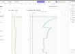
When calculated, the software outputs the following graphs:
- Thrust on reinforcement;
- Safety factor on reinforcement;
- Safety factor for failure;
- Pull-out resistance;
- Ultimate strength of the material.


The “Export to Word” command in “Report” allows the generation of a detailed calculation report, in which the results of the analysis are presented in a table form, in addition to the theoretical notes.


Mechanically Stabilized Earth – MRE
Design and verification of mechanically stabilized earth with metallic elements, geomembranes, gabions, geogrids and Wooden Piles both in static and seismic conditions.
The software allows you to easily create the input through a series of dedicated tools such as automatic generation of reinforcement positions, generation of the reinforced soil profile and choosing between a steady gradient profile or terraced profile.