In the design of road and rail embankments on fine-grained or very fine-grained soils, it is necessary to understand the settlements to overland the time. This is because, in the case of water infiltration, the drainage process takes place very slowly in the medium and long term.
The problem is particularly felt in the sections adjacent to the shoulders of the viaducts and in the expansion of pre-existing investigations for obvious reasons.
Therefore, the goal is to speed up the process of the settlement course up to the drainage process or strengthen the terrain. Currently, there are various techniques suitable for the above-mentioned purpose: Traditional ones by applying drainage and/or preloads and land consolidation techniques with the insertion of columnar reinforcements (pillars, deep mixing, jet grouting, stone columns, etc.)
Solutions to intervene in the settlements
The weak mechanical properties of the foundation soils, together with significant loads deriving from the corresponding weight of those detected, can actually induce instability phenomena or lead to large and prolonged settlements, capable of compromising the functionality of the work.
Traditional techniques involve the use of vertical drains, possibly combined with a pre-loading phase. The application of the load has the effect of “pressing” the ground removing water.
Recently, solutions are proposed that, instead of aiming at accelerating the drainage process, aim to strengthen the soil in anticipation of subsidence that would occur over time: This is the application of rigid cylindrical elements consisting of piles or columns. On the positive side, it isn’t necessary to wait long periods due to the movement of the soil, but the cost increases.
Strengthening through foundation pilots
In the application of pilots, the loads are transferred to the head of the latter, trying to increase the central distance and reduce the concentration of tangential forces and distortion in detection that could generate irregularities in the road surface.
An alternative to pillars is the introduction into the soil of various materials such as concrete, sand, gravel, grout, etc. combined with several actions such as tapping, drilling, injection, mixing, vibration, replacement, and compaction. They create cylindrical elements, so-called “columnar reinforcements”: deep mixing, jet grouting, stone columns and all variants associated with them.
Deep Mixing
This involves the mechanical mixing of lime and/or cement into the soil through a mechanical drill with rotating blades. If the mixture of lime and cement is added as a powder, dry mixing is usually used for saturated clay soils, if it is previously mixed with wet mixing water.
Jet grouting
It consists of injecting liquid mixtures, designed at high speed. This process means that there are phenomena of decay, mixing and/or soil permeability, which, with adhesion and stiffening, produce a cemented soil element of almost cylindrical shape

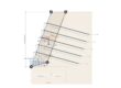
Fig. 1 – The application of jet grouting on embankment road
Stone columns
Stone columns are columns of sand and/or gravel and have the dual property of water drainage and soil stiffening. They are applied through a vibrating probe that penetrates the ground by thickening the surrounding soil and filling the hole with sand and gravel.

Fig. 2 – Railway finding recognized on stone columns
A different technique for making stone columns, used in Eastern European countries to strengthen foundations [KWIECIEE and SKI, 2008], consists of dynamic compaction of coarse-grained material with the help of a hammer weighing about 10 tons fallen from maximum heights of 15 m. depending on the characteristics of natural soils, it is possible to reach maximum depths of 4-6 m.


Bearing capacity and Settlements of mat foundations on piles
The software DeepFound offers the possibility to calculate the payments of mat foundations on piles using the computation method PDR proposed by Poulus (2000), deriving from the combination of the methods Poulus and Davis (1980) and the technique Randolph (1994).
Vertical drains
Vertical drains are important routes for the migration of groundwater, when the consolidation process is to be accelerated by a preload, in low-permeability soils.
The installation of drains is usually preceded by the preparation, on the imprint of the body of the researcher, of a drainage mat, with the double function of the working plan and the collection and disposal of water transmitted through the drains. As for the types of drainage and their installation methods, historically, the drainage made with sand poles was more widespread due to their modest construction cost.

Fig. 3 – The application of drains
The size of the aid
In sizing works of this type, it should be borne in mind that the mechanical behavior of a foundation armed with column elements is dependent on the interaction between natural soils and columns, each with its own characteristics.
In addition, the mechanical characteristics, in addition to the factors mentioned above and the material, vary depending on the depth of the column which is strongly influenced by the way of execution. The geometrical arrangement of interventions (fig. 4) can lead to a load distribution from a higher yield area to a more rigid one.
In order to define the length of the columns, it’s necessary first to identify and characterize the significant volume of the foundation, that is, that portion of land which, as a result of the construction and exploitation of the research, will be affected by significant deformations.

Fig. 4 – The geometry of a typical column reinforcement system (a. vertical section; b. triangular and square planimetric appearance)
The design of a column reinforcement system for the foundation of an inspector thus begins with the definition of a series of characteristics, geometries and mechanics, the combination of which depends on the effectiveness of the measure taken.


Geotechnical and F.E.M. analysis system – GFAS
.F.A.S. (Geotechnical and F.E.M. analysis System) software for the mechanical analysis of soil using the finite element method.
The traditional methods of analysis based on the concept of LIMIT EQUILIBRIUM (LEM) do not allow the determination of stresses and deformations in the analyzed volumes.
These limitations have led to the need to integrate conventional analysis with analysis based on numerical models.
These methods use the numerical evaluation of the problem and do not require simplifications to the calculation.
GFAS Extension brings additional features to finite element software like water flow analysis.
How to predict the settlements in time
GeoStru has among its applications Geoapps the online application “progress of subsidence in the presence of vertical drain“, which allows through a few input data to generate graphs of the trend over time of the degree of consolidation and subsidence (Fig.5)

- Andamento nel tempo consolidazione = the evolution over time of consolidation
- Andamento nel tempo cedimenti = the evolution over time of deformation
- Drain sense = no drainage
- Con dreni con efficacia ridotta = with low efficiency drainage
- Cone drain = with drainage
- Tempo di consolidazione t(anni) = timp de consolidare t(years)
Fig. 5 Output of the Geoapp progress of settlement in the presence of vertical drains
The user is tracked step by step in the data entry according to the current scheme:

Fig. 6 – Diagram used in Geoapp
Where with:
- h1 = thickness of the drainage layer
- h2 = thickness of the layer without drainage
- h = drainage path layer without drainage
- CV = Coeff. vertical consolidation
- Ch = Coeff. horizontal consolidation
- dw = equivalent drainage diameter
- i = distance of drains
You can choose the type of drainage between the pre-made belt or sand, with a database included with the reference values of the type, such as the diameter of the drain, thickness, width, permeability depending on the material, etc.
The calculation model provides for the choice of the arrangement of square mesh drains or of the quincunx (Fig. 7):

- Dreni verticali = vertical drainage
- Disposizione dei dreni a quinconce = quincunx drains arrangement
- Disposizione a maglia quadrata = square mesh arrangement
- Condizioni al contorno = limit conditions
- Se la base e impermeabile = waterproof base
Fig. 7 – Drainage arrangement model
Other input data are the form coefficient, predictable settlement expressed in cm, horizontal permeability coefficients and filter, the diameter of the disturbed area, and drain mode (one end or two).
The result will be as shown in Figure 5, where the trends at the time of consolidation and settlement are highlighted in 3 different cases: No drainage channels, with low-efficiency drainage channels (taking into account the effect of the hydraulic resistance of the drain is the rehash of the soil) and with drainage channels.
Fault in the presence of vertical leaks. The application allows to the analysis of the decreased course over time in soils with fine grains in the presence of vertical leakage. The ability to save and upload the project, graphical creation of the trend of subsidence and consolidation over time, and export report full calculation of indices
In addition to saving and opening work projects, the application allows you to draw up a complete calculation report with the theoretical indices of the model used and output results in a detailed way as value tables used in the creation of graphs.

Settlement course in the presence of vertical drains
The application allows for analysis of the settlement over time in soils with fine grain in the presence of vertical drainage.
The ability to save and upload the project, graphic creation of the trend of subsidence and consolidation over time, and export the full index calculation relationship in .docx format