The permeability test in the oedometer cell is aimed at determining the coefficient of permeability (K) through direct measurement under variable hydraulic loading during the oedometric test.
Advanced configuration of the oedometer cell
In questa sperimentazione, si impiega una cella edometrica con una configurazione leggermente diversa rispetto al modello convenzionale, poiché presenta un ingresso pratico all’interno della cella stessa (Fig. 1). Questo ingresso è connesso alla pietra porosa di base, consentendo l’inserimento di una buretta esterna. Inoltre, la cella è dotata di un anello di tenuta a guarnizione o-ring, posizionato esternamente tra la pietra porosa e la piastra superiore di centraggio del campione in esame. Vi è anche un foro di uscita superiore che assicura il controllo e il mantenimento del livello idraulico (Fig.1 e 2).

This particular configuration of the oedometer cell is essential to ensure the precision of measurements and the stability of the test environment during execution. The practical inlet allows for easy manipulation of the cell, while the o-ring sealing ring helps prevent unwanted fluid leaks. The upper outlet hole is crucial for maintaining the correct hydraulic level inside the cell, ensuring ideal conditions for oedometer analyses.
Use of Burettes for Hydraulic Control.
The equipment is further complemented by the addition of one or more burettes, whose cross-sectional area usually ranges from 0.05 to 5 cm², allowing a hydraulic excursion on the order of 50 cm (Fig. 3). These burettes are equipped with a millimeter-scale graduated in length rather than volume, with increments increasing from the base upwards.
The burettes are positioned vertically and connected to the oedometer cell through a transparent tube and a valve, ensuring precise control of the hydraulic input. This configuration ensures accurate adjustment of the hydraulic head during experiments, thereby contributing to the precise collection of geotechnical data and the attainment of reliable scientific results.

Preparation of the oedometer cell
The procedure for preparing the oedometer cell before inserting the sample differs from the conventional method.
Below, we outline the key steps for this critical phase:
1.Adjustment of the graduated burette: Begin by carefully adjusting the position of the graduated burette so that the zero reading precisely coincides with the level of the drainage hole in the cell.
2. Filling and water flow: Next, proceed to fill the burette with distilled water and open the connecting valve. This allows the fluid to flow down to the lower porous stone inside the oedometer cell.
3.Complete saturation of the circuit: It is crucial to pay extreme attention to ensuring that the entire circuit is completely saturated. The presence of air bubbles can negatively impact the proper conduct of the test.
4.Leveling and removal of excess water: Subsequently, restore the water level in the burette to the desired value and then close the valve. Any excess water in the lower porous stone must be carefully removed
Phase 1 – Oedometer Compression
Once the preparation of the oedometer cell is completed, the next step involves applying the load increments as specified in the standard procedures (Fig. 4). Precision and attention to detail in this preliminary phase are crucial for obtaining reliable results in geotechnical analyses conducted with the oedometer cell.

Each stage of applying load increments provides the opportunity to measure the coefficient of permeability at predetermined consolidation loads, provided that the completion of the process has been previously confirmed. The significance of this measurement lies in avoiding interference from the hydraulic gradient generated during the consolidation process, thus the valve connecting the burette and the oedometer cell must be closed. It is important to highlight that the first phase, “oedometer compression,” a prerequisite to the actual permeability measurement, will be considered concluded after 24 hours or after the settlement of the specimen under the vertical load has stabilized.
Phase 2 – Direct Permeability Test
The procedure for conducting the permeability test is as follows:
1. Preliminary hydraulic load: Begin by adding a sufficient amount of distilled water to achieve a hydraulic load on the order of 50 cm. It is crucial to ensure that the water temperature is in equilibrium with the ambient temperature, and record this value as the reference temperature for the test.
2. Measurement of the water level: Record the water level inside the burette.
3. Opening the valve and starting the timer: Open the valve located at the base of the oedometer cell and simultaneously start the stopwatch to record the time.
4.Achievement of the desired hydraulic load.: We continue the measurement until we reach a hydraulic load on the order of 10-15 cm. At this point, we close the valve and apply the oedometer load to prepare for the subsequent permeability measurement.
For each recorded hydraulic load value, we calculate the permeability coefficient (indicated as “k”) using the following expression:
k=(H0) – δH) ∙ ab/As ∙ (loge L0/Lt )/(tt-t0) ∙ 10-2
H0 = the initial hydraulic load (cm)
δH = the change in hydraulic load (cm)
ab = the cross-sectional area of the burette,
As = the cross-sectional area of the specimen ,
L0 = the initial length of the flow path,
Lt = the current length of the flow path tt
t0 =the initial time corresponding to the reading L0 (sec)
tt = is the subsequent time corresponding to the reading Lt (sec)
The accurate execution of this procedure ensures precise measurements of the permeability coefficient and contributes to the accuracy of geotechnical assessments conducted in the experiment.
Results
The results obtained from the oedometer cell permeability test provide permeability values at different loads. Specifically, the application of each individual load, appropriately calculated based on the lithostatic load at the sampling depth, ensures the precise permeability value obtained from the test. Moreover, if the horizon from which the sample was taken is granulometrically homogeneous, it is possible to obtain permeability values at different depths by varying the load.
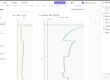
In particular, in the graph below (Fig. 5), it is highlighted that the specimen subjected to the test was consolidated under an initial load of 0.25 kg/cm2 for a duration of 24 hours. Subsequently, the actual permeability test was conducted, measuring the water level drop in the graduated burette at predetermined time intervals. This testing procedure was performed for each load step, in our case: 0.25 kg/cm2, 0.50 kg/cm2, 1 kg/cm2, 2 kg/cm2. From the graph, it is possible to obtain the permeability value in m/sec for each applied load step and, therefore, for each corresponding depth interval.

Bibliography and acknowledgments
ASTM (1985) – Test designation D4546 – Standard Method for One-Dimensional Swell or Settlement Potential of Cohesive Soils. Vol. 04.08.ASTM Philadelphia, USA.
BS 1377: Part5 (1990) – Compressibility, Permeability and Durability Tests. Special Report 163, Transportation Research Board, pp.4-12.
Black D.K. and Lee K.L. (1973) – Saturated Laboratory Samples by Back Pressure. Journal of the Soil Mechanics and Foundations Division, ASCE, Vol.99, n.SM1.
In particular, we would like to express our gratitude to the geotechnical testing laboratory I.P.G. in Castrolibero (CS) for their availability in facilitating the practical implementation and understanding of the analyses described above. Special thanks to S. Soleri for the valuable explanations.